

Reception Furniture /Reception Desks
C01 / PRODUCT CONFIGURATIONS
Custom Solid Surface
Reception Desks
Choose the form.
Confirm the working space.
Compare straight, curved and return references. Resolve equipment, usable dimensions and site access for the selected desk.
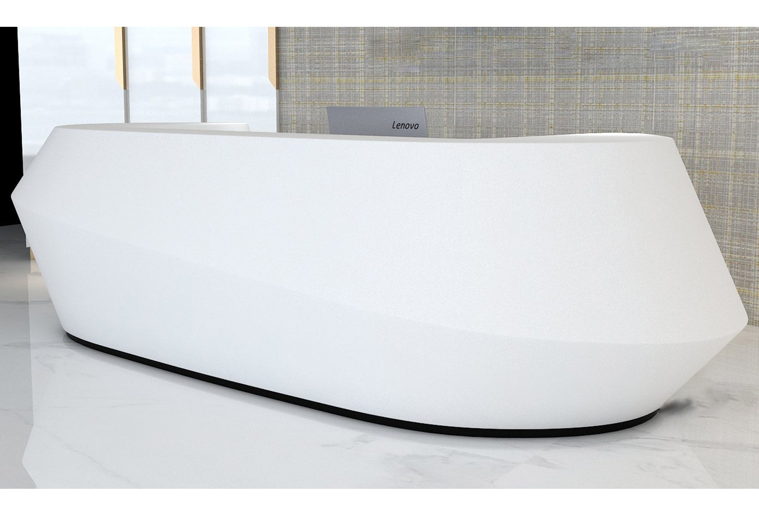
YHS PROJECT LOGIC / RECEPTION DESKS
Form×Working space×Equipment×Site route
C02 / PRODUCT REFERENCES
Find a starting point.
Then test the working plan.
Browse by visible form. Use a selected reference to start the project review.

Gray Marble Solid Surface Reception Desk for Commercial Interiors
View Product
Marble Look Solid Surface Hotel Reception Desk
View Product
White Marble Solid Surface Beauty Salon Reception Desk
View Product
Half-Round White Solid Surface Reception Desk for Offices
View Product
White Creative Solid Surface Corporate Reception Desk
View Product
Small White Creative Solid Surface Front Desk for Company Lobbies
View Product
Wood Accent Solid Surface Reception Desk for Modern Offices
View ProductSelect a configuration to compare its working plan. Confirm the form, working dimensions, equipment and construction for your selected product.
C03 / CONFIGURATION + SELECTION
The outside shape
does not define the inside.
Choose a form, then resolve the working requirements that shape cannot prove.
Straight reception desk
Start here when a linear public frontage fits the arrival and working plan.
- 01Usable depth + equipment footprint
- 02Occupied positions + open storage
- 03Staff entry + shared-equipment access
Curved reception desk
Start here when the visitor approach or room geometry calls for a shaped frontage.
- 01Inner working radius + usable depth
- 02Monitor reach + occupied positions
- 03Entry + feasible joint positions
Return / wraparound desk
Start here when the brief needs extra working sides or a return for equipment and storage.
- 01Internal circulation + staff entry
- 02Open drawers + equipment bays
- 03Module joints + service access
Multi-station is capacity. Modular is a build/delivery strategy. Neither is a separate shape.
01Occupied staff zone02Open storage envelope03Staff/service entry04Equipment + handover
01Occupied staff zone02Open storage envelope03Staff/service entry04Equipment + handover
01Occupied staff zone02Open storage envelope03Staff/service entry04Equipment + handover
C04 / CRITICAL INTERFACES
Check the interfaces
inside the selected form.
What must be confirmed before this can be manufactured correctly?
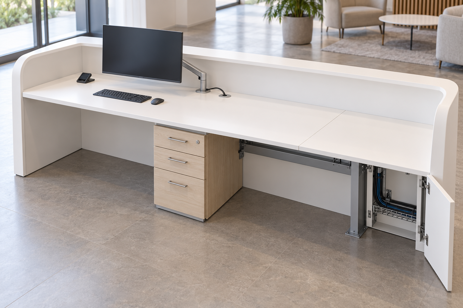
INTERFACE MAP / 01–04Confirm in the shop drawing
01Monitor mount + usable depth
Overlay the monitor arm, keyboard zone and equipment footprint within the usable worktop depth.
Confirm the model before drilling.
02Cable entry + removable access
Check the grommet, cable path, cabinet clearance and panel removal together.
Access must remain after storage is installed.
03Surface joint + contact edge
Locate the joint against the selected form, module breaks, edge profile and finish.
Approve the visible detail before release.
04Internal support + knee space
Review support, open drawers and equipment bays within the occupied working space.
Support must preserve the approved working clearance.
Coordination concept. Actual equipment, support, joints and service provisions follow the approved project detail.
C05 / BUILD ANATOMY
Surface. Support. Service.
The visible face and supporting assembly must be resolved together.
01Solid-surface shell02Local backing03Project support04Removable panel
01
Surface + visible details
Approve the material sample, edge profile and joint position. Finish and pattern choices affect the visible detail.
02
Backing + support zones
Select backing and support for the actual span, loading and fixing. Preserve knee space and equipment bays.
03
Storage + service access
Coordinate cabinet opening, panel removal and equipment replacement before the supporting assembly is released.
For the selected desk, request the approved detail and relevant checks.Review the project record checklist →
C06 / PROJECT RISK MAP
Resolve the decisions
that become site changes.
Keep the risk, consequence, control point and evidence connected.
01Overall length mistaken for usable capacity
Risk
A desk is selected by outer dimensions without an occupied working plan.
Project consequence
Staff positions, open drawers and equipment can conflict.
YHS control point
Overlay the working positions, usable depth, storage travel and equipment before fixing dimensions.
Evidence required
Dimensioned working plan + equipment footprints.
02Outer curve mistaken for working space
Risk
The outside radius is chosen without inner geometry or staff entry.
Project consequence
The desk may restrict monitor reach or internal circulation.
YHS control point
Approve the inner radius, usable depth and entry with occupied positions and open storage.
Evidence required
Inner working plan + key sections.
03Lighting hides a service problem
Risk
Drivers and connections are placed after storage and the face are fixed.
Project consequence
Replacement access may require dismantling the finished frontage.
YHS control point
Locate the lighting channel, driver and removable panel before surface release.
Evidence required
Lighting detail + access drawing + electrical scope.
04Module breaks follow crate size alone
Risk
Joints are fixed without the building route and visible finish.
Project consequence
A module may not reach the floor or a joint may interrupt the intended face.
YHS control point
Review packed size, weight, joint appearance and assembly order as one decision.
Evidence required
Module/joint plan + route survey + approved finish detail.
Agree the approval owner and release revision for each control point. The listed records are required evidence, not records supplied by these concept illustrations.
C07 / BEFORE WE BUILD
Freeze the selected detail.
Then release manufacture.
These are production-release decisions. You can start an initial review before they are all complete.
01
Form + quantity
Selected reference, quantity, working positions and reception task.
02
Usable dimensions
Overall dimensions, worktop depth, inner radius and staff entry.
03
Equipment + openings
Final models, mounting/cut-outs, service clearance and cable entry.
04
Finish + details
Approved sample, edge, joints, logo and lighting where required.
05
Storage + support
Drawer travel, equipment bays, support/fixing and removable panels.
06
Modules + route
Module joints, packed dimensions/weights and installation responsibility.
Agree the approval owners.
Project team: site, equipment and finish approvals. Furniture scope: fabrication detail and module plan. Site trades: utilities, handling and installation. Confirm the actual responsibilities in the project scope.
DELIVERY IS A DESIGN INPUTA desk that fits the room
A desk that fits the room
must reach the room.
Plan module breaks around the entire building route, joint appearance and site assembly sequence.
01 / Ground floor + receiving
Confirm unloading responsibility, door openings, corridor turns and the final room approach against packed size and gross weight.
02 / Upper floors + elevator
Provide clear door width/height, cabin width/depth/height and rated load. Include the handling equipment in the route review.
03 / Stairs + turning space
If stairs are required, provide clear stair width, landings, turning/corner dimensions and headroom. Agree handling limits, method and responsibility.
04 / Site assembly + installation window
Agree module order, fixing, local joint work, utilities connections and surface protection with the site team.
C08 / READY TO QUOTEChoose a reference.
Choose a reference.
Start with what you have.
Share a product reference or sketch and the reception task. Identify the equipment and site questions that are still open.
Final equipment and production details can be resolved during project review.
ENOUGH TO START AN INITIAL REVIEW
- Reference image, sketch or available drawing
- Application + approximate size / quantity
- Project location + receiving floor
- Target installation date + known constraints
What must be confirmed before production?
Approved drawings and revision; actual dimensions; material/finish; equipment and utilities; module and packing plan; site access and installation responsibilities.
Initial estimates should identify assumptions and exclusions. Fabrication follows the confirmed project scope.