
Reception furniture
built around arrival.
Coordinate the first impression with staff workflow, equipment, brand details and the route into the building.
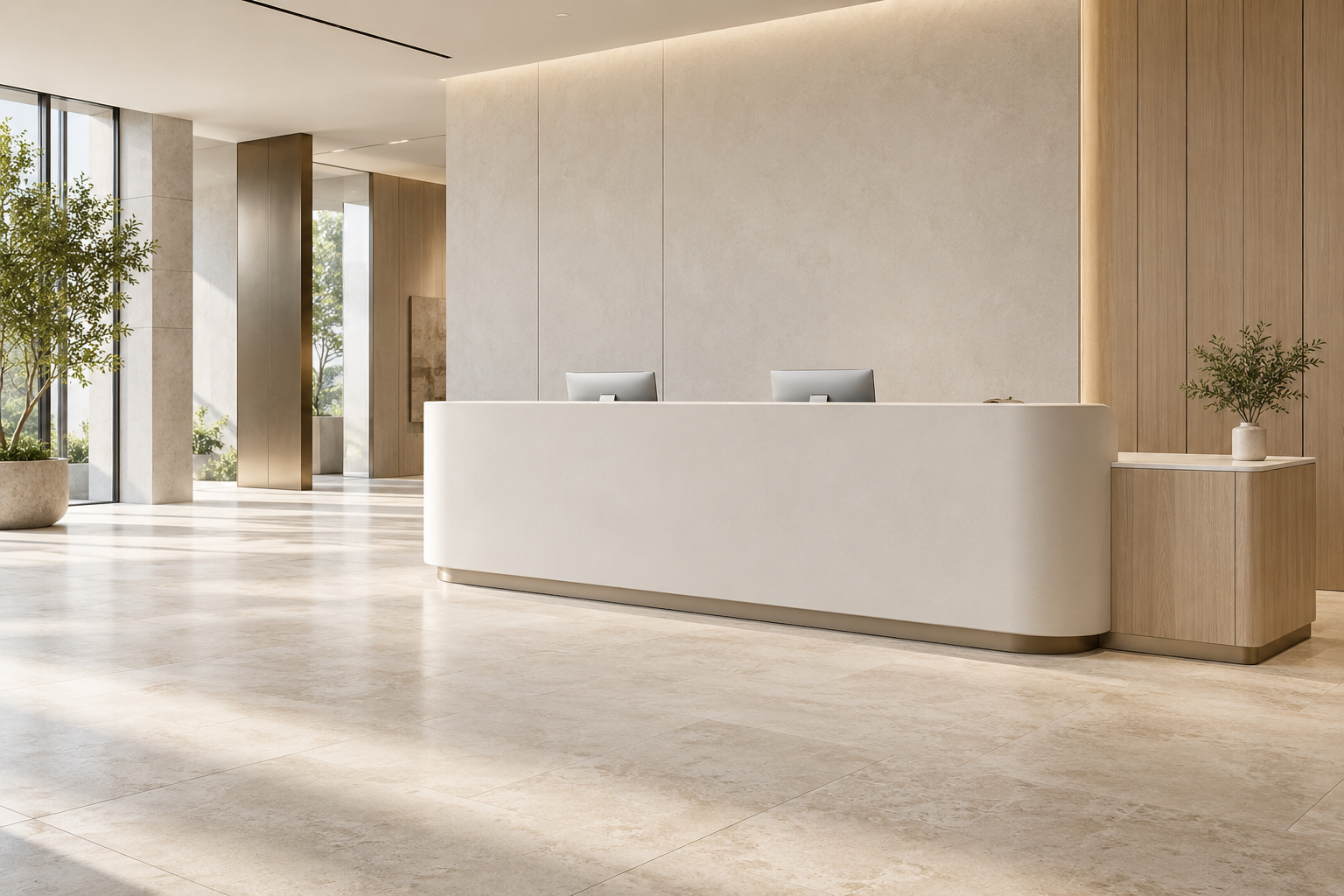
Arrival×Staff workflow×Brand detail×Delivery
Plan both sides
of the first impression.
Visitor arrival, staff use and brand details belong in one coordinated plan.
A reception desk connects the visitor’s arrival with the staff’s working plan.
Arrival + handover
Locate the greeting point, queue and document exchange without obstructing entrance doors or lift lobbies.
Occupied working space
Overlay staff positions, monitors, open drawers and shared equipment before fixing the footprint.
Service + brand coordination
Keep staff entry and replacement access clear. Coordinate artwork, lighting and finish on the same elevation.
A clean frontage.
A working side that works.
What must be confirmed before this can be manufactured correctly?
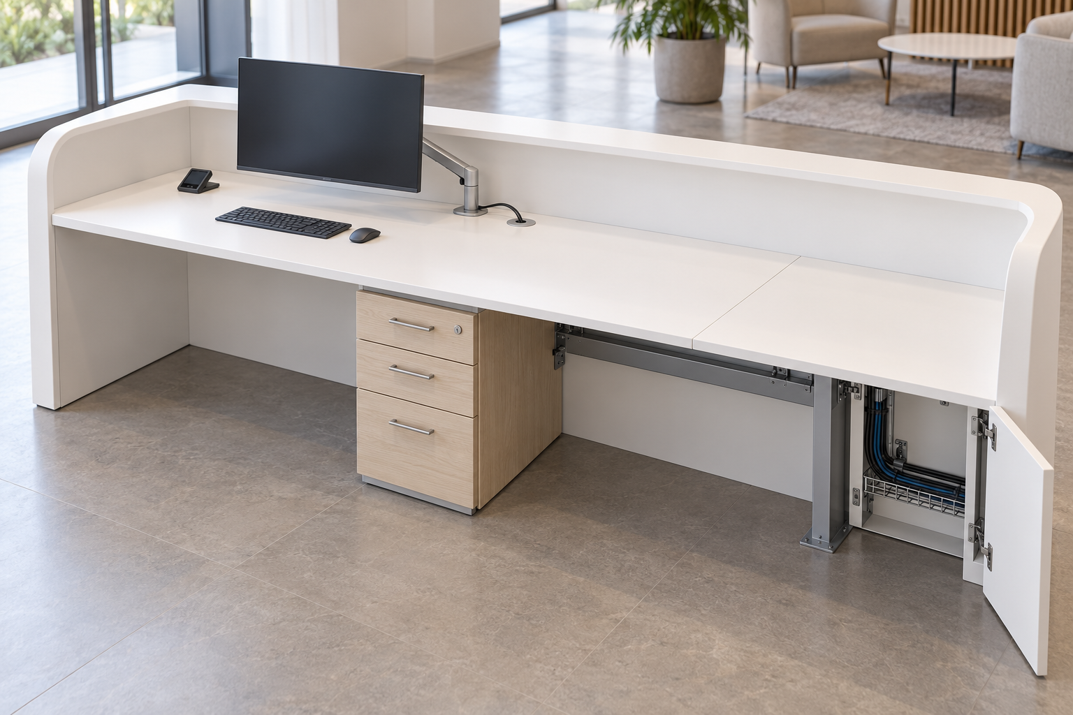
01Equipment + handover
Confirm the visitor task, monitor sightline, device footprint and handover level with the operations and IT teams.
02Power, data + service access
Locate building connection points, cable entry and removable panels. Check access after storage is installed.
03Finish + joint alignment
Coordinate the visible joint, logo scale and lighting line with the approved material sample and elevation.
04Support + usable space
Resolve the support, fixing and service cavity around staff use and equipment.
Coordination concept. Actual equipment, support, joints and service provisions follow the approved project detail.
Surface. Support. Service.
The visible face and supporting assembly must be resolved together.
Surface + visible details
Approve the material sample, edge profile and joint position. Finish and pattern choices affect the visible detail.
Backing + support zones
Select backing and support for the actual span, loading and fixing. Preserve knee space and equipment bays.
Storage + service access
Coordinate cabinet opening, panel removal and equipment replacement before the supporting assembly is released.
Resolve the decisions
that become site changes.
Keep the risk, consequence, control point and evidence connected.
01Brand approval on separate revisions
Artwork and lighting are approved separately from the furniture elevation.
Fixings, openings or light lines may miss the intended alignment.
Coordinate artwork, finish, lighting and service access on the released elevation.
Approved elevation + artwork/lighting detail.
02Equipment selected after openings are cut
Final hardware models are missing at fabrication release.
Equipment may not fit or remain accessible for replacement.
Keep affected openings pending until the model, mounting dimensions and service clearance are approved.
Equipment schedule + released drawing + relevant fit-check record.
03Arrival plan stops at the front elevation
The greeting point is fixed without queue, doors or staff entry.
Visitors and staff circulation can conflict.
Review the marked arrival and occupied working plan before freezing the footprint.
Arrival plan + working layout + service-position approval.
04Modules fixed before the site route
Receiving floor, handling route or installation window is unresolved.
The module may not reach the room or the agreed installation period.
Resolve packed dimensions, weight, joints and handling before module release.
Route survey + module/packing plan + agreed site responsibilities.
Agree the approval owner and release revision for each control point. The listed records are required evidence, not records supplied by these concept illustrations.
Connect the detail
to the record.
Link manufacture, checks and delivery to the approved drawing.
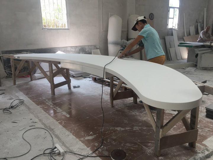
General workshop reference. It does not replace the project records for your selected desk.
For your selected desk, request records that can be traced to its scope and drawing.
Drawing + release
Furniture layout, coordinated interfaces, approval owner and the revision released for manufacture.
Finish + visible detail
Material sample, joint/edge detail, logo artwork and lighting access linked to the approved elevation.
Fit + access checks
Relevant checks against the actual equipment model and approved drawing.
Packing + site route
Packed module dimensions, gross weights, handling route and agreed installation responsibilities.
Freeze the selected detail.
Then release manufacture.
These are production-release decisions. You can start an initial review before they are all complete.
Task + layout
Arrival, handover, staff positions and project-required service provisions.
Site dimensions
Furniture footprint, wall/floor junctions, doors and fixing conditions.
Material + brand
Approved sample, edge/joint detail, artwork and lighting elevation.
Equipment + utilities
Final models, mounts/openings, power/data entry and approval owners.
Working side + access
Knee space, storage travel, staff entry and equipment replacement.
Modules + delivery
Released revision, module breaks, packed route and installation window.
Project team: site, equipment and finish approvals. Furniture scope: fabrication detail and module plan. Site trades: utilities, handling and installation. Confirm the actual responsibilities in the project scope.
A desk that fits the room
must reach the room.
Plan module breaks around the entire building route, joint appearance and site assembly sequence.
01 / Ground floor + receiving
Confirm unloading responsibility, door openings, corridor turns and the final room approach against packed size and gross weight.
02 / Upper floors + elevator
Provide clear door width/height, cabin width/depth/height and rated load. Include the handling equipment in the route review.
03 / Stairs + turning space
If stairs are required, provide clear stair width, landings, turning/corner dimensions and headroom. Agree handling limits, method and responsibility.
04 / Site assembly + installation window
Agree module order, fixing, local joint work, utilities connections and surface protection with the site team.
Bring the brief.
Start with what you have.
Share the arrival brief, a sketch or a reference image. The first review can identify the furniture scope and the coordination points still to resolve.
Final equipment and production details can be resolved during project review.
- Reference image, sketch or available drawing
- Application + approximate size / quantity
- Project location + receiving floor
- Target installation date + known constraints
What must be confirmed before production?
Approved drawings and revision; actual dimensions; material/finish; equipment and utilities; module and packing plan; site access and installation responsibilities.
Initial estimates should identify assumptions and exclusions. Fabrication follows the confirmed project scope.