
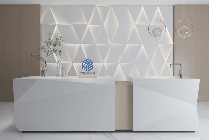
COMMERCIAL SPACE COLLECTIONS
Solid Surface
Commercial
Space Products
Choose the element.
Resolve its connections.
Custom solid-surface elements for ceilings, walls and column surrounds. Confirm the substrate, fixing and access before the visible form is released.

C02 / PRODUCT REFERENCES
Start with the application.
Compare the right elements.
Explore current solid-surface product references. Compare the application, form and interface conditions to find a starting point for your project.
Product scope and final details follow the selected item.
C03 / APPLICATION SELECTION
One material language.
Different build decisions.

Ceilings + overhead features
Confirm support responsibility, fixing points and maintenance access.

Wall cladding
Confirm surveyed substrate, adjoining finishes and panel replacement.

Column surrounds
Confirm available clearance, split positions and installation sequence.
C04 / INTERFACE MAP
A clean radius starts with
a confirmed substrate.

01
Surveyed substrate
Confirm the actual profile, out-of-plumb variation and available clearance.
Review conditions
Record surveyed centre lines, floor-to-ceiling conditions and adjoining finishes. Overlay the surveyed substrate profile with the intended finished radius before fixing the panel line.
Record to confirm: Surveyed section, profile and available-clearance record.
02
Fixing provision
Agree the support detail, allowable fixing zone and approval owner.
Review conditions
Confirm the substrate and permitted fixing locations, support responsibility, loads and installation method with the responsible project team. Release the selected fixing detail only after the named owner approves it.
Record to confirm: Approved fixing detail and responsibility confirmation.
03
Split + joint
Coordinate seam locations with module size and installation sequence.
Review conditions
Review panel divisions, visible joint positions, tolerances and joining method against the surveyed geometry and receiving route. A continuous appearance does not establish a joint-free assembly.
Record to confirm: Panel split and joint schedule linked to the approved revision.
04
Access + replacement
Keep required services reachable and plan panel removal.
Review conditions
Confirm which panels can be removed, tool clearance, service access zones and the replacement route. Check that fixings and adjacent finishes allow access without dismantling unrelated work.
Record to confirm: Access-zone and removable-panel review.
C05 / MATERIALS + SUPPORT
A formed surface.
A project-specific support strategy.


Surface + edge
Confirm material, finish, forming radius and visible joint treatment.
Selected backing + fixing
Select the support and fixing method for the approved geometry and loads.
Building connection
Review the substrate and adjoining finishes with the responsible project team.
C06 / PROJECT RISK MAP
Resolve the dependency.
Prevent the site change.

Design radius
Proposed outer form and visual appearance.

Surveyed profile
Actual substrate profile and available clearance.

Revised panel line
Adjusted panel line and support strategy.
Illustrative coordination sequence
- Risk
The outer radius is fixed before the substrate is surveyed.
- Consequence
Fixing space or service access is lost.
- Control point
Overlay survey, support, joints and access zones before release.
- Record to confirm
Surveyed section + fixing detail + approved revision.
A continuous appearance is treated as a joint-free assembly
- Risk
The visual concept is taken as a promise of an uninterrupted panel.
- Consequence
Manufacturing, transport or installation requires a split that appears late on site.
- Control point
Agree panel size, joint positions and the installation sequence before manufacturing.
- Record to confirm
Approved panel division drawing + joint detail + module schedule.
A formed module cannot reach its final position
- Risk
Final dimensions are released without checking the packaged receiving route.
- Consequence
The module cannot clear the lift, landing or doorway, delaying installation.
- Control point
Prove the complete route with packed module dimensions and gross weight; revise modules before release.
- Record to confirm
Route measurements + module/packing schedule + agreed handling sequence.
C07 / BEFORE WE BUILD
Freeze the coordinated detail.
Then release manufacture.

- Project
- Commercial space element
- Drawing
- Reference detail
- Revision
- For manufacture
- Scope
- Geometry, support, joints, interfaces and access
- Approval
- Confirmed by project owner
Survey + geometry
Actual profile, centre lines, clearances and adjacent conditions.
Surface + support
Panel split, substrate detail, fixing method and material.
Interfaces + responsibilities
Service openings, access zones and named approval owners.
Module + receiving route
Module size, packed dimensions, gross weight and delivery route.
Plan the module.
Prove the route.

Ground floor
Receiving opening, unloading and handling route.
Route conditions
Confirm the receiving floor and the unloading point, door and corridor clearances, delivery vehicle access, handling method and responsible team before release. Check the packed module through every turn and doorway.

Elevator
Door and cabin dimensions, load limit and receiving floor.
Route conditions
Record the elevator door width and height, cabin width, depth and height, rated load and receiving floor. Check packaged module dimensions and gross weight, including handling equipment, against the usable lift space and load limit.

Stairs
Clear width, landings, headroom and turning dimensions.
Route conditions
Measure stair clear width, landing size, clear headroom and every turning dimension. Review the packaged module envelope and carrying or lifting method through the complete route; do not rely only on its final installed dimensions.

Assembly
Module joints, packed size, gross weight and lifting sequence.
Route conditions
Freeze module and packaging dimensions, module IDs and gross weight. Agree unloading, handling and lifting responsibility, joining method, assembly and installation order, temporary holding area and working window with the site team.
Crate size alone does not define a deliverable module.
C08 / READY TO QUOTE
Bring the reference.
Show us where it belongs.
Share the element, intended location and available drawings. Identify what is confirmed and what still needs coordination.
Application + quantity
Tell us what you are planning.
Drawing or reference
Share plans, sketches or similar projects.
Substrate + interfaces
Confirm what is known and what needs review.
Receiving floor + target date
Include access, handling and your programme.